
Intro to Digital Systems
- Jan 25, 2020
- 19 min read
Updated: Aug 3, 2020
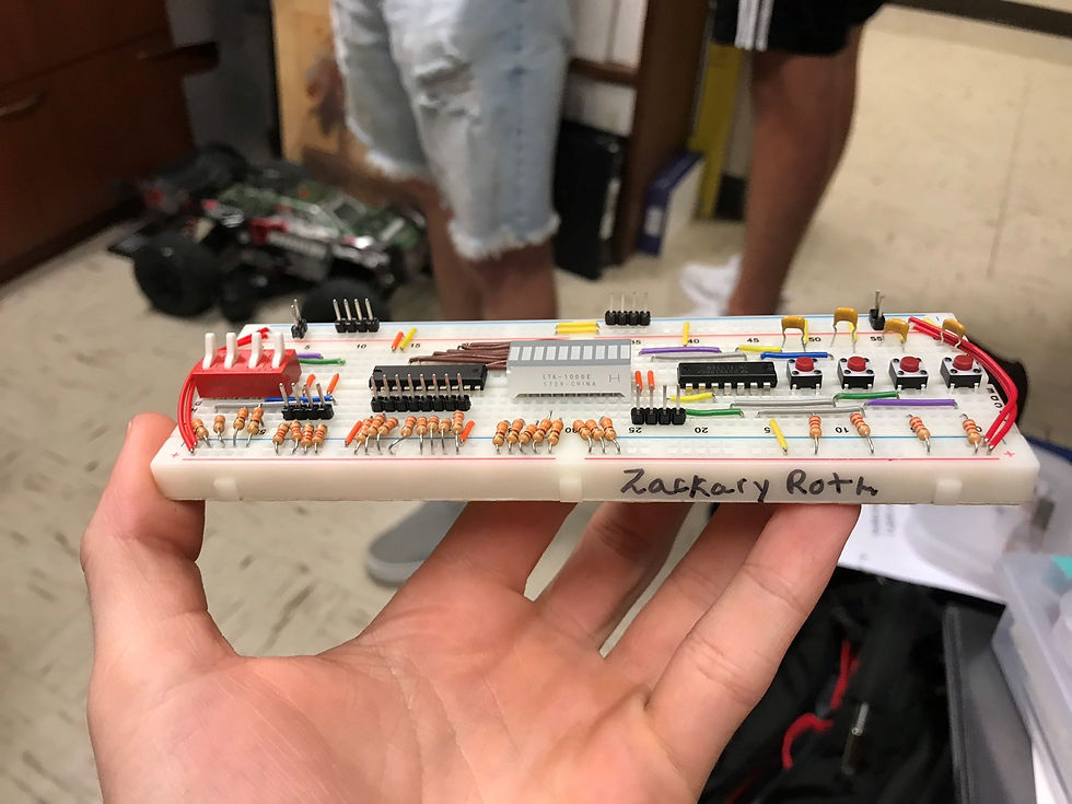
The MicroController I worked with was the Atmega2560 and I used Atmel studios (C programming software) to program it to do different tasks.

Atmega2560
16 MHz clock speed
256 KB Flash Memory
54 Digital I/O Pins
8 KB SRAM
Labs
(All Serial Files were provided to the students with a select few that required me to edit them due to wrong calculations or missing code)
Lab 1:
/*
* Lab_1.c
*
* Created: 8/29/2019 11:48:11 AM
* Author : rothz
*/
#include <avr/io.h>
int main(void)
{
DDRC = 0xFF; // all bits set for output
DDRA = 0x00; // all bits set for input
PORTA = 0xFF; // turn on pull-up resisitors
/* Replace with your application code */
while (1)
{
PORTC =PINA; // echo value from port A to port C
}
}
Lab 2:
I created a lights and switches board.
Lab 3:
Files Got Corrupted
Lab 4:
/*
ECET 179 - Intro to Digital Systems
Lab Exercise: 5
Name: Zackary Roth
Created: 9/12/2019 11:30:15 AM
Lab Date: Thursday 11:30
IO Connections: PORTA is used as an input
PORTC is used as an output
Description: This program testes loops and other decision processes on the ATMEL 2560 and is the final
code for procedure 7. the program starts with ports A and C initialized followed by an infinite loop that
contains the main code. within while(1)it checks if a button is pressed and turns LEDS on in a sequence.
Key Takeaways: it is important to understand the difference in the function of loops within C to figure what loop to use for a specific application.
another thing to takeaway after the lab is that flow charts are step by step guides to writing and building code
*/
#include <avr/io.h>
#include <stdio.h>
#include "serial.c"
#define F_CPU 16000000L
#include <util/delay.h>
int main(void)
{
init_UART();
printf("STDIO Test Program for Lab 4- Zackary Roth \n\r");
DDRA = 0x00; // initializing port A as input
PORTA = 0xFF; // pull up resistor
DDRC = 0xFF; // initializing port c as output
while (1) // making program constantly run
{
while(PINA != 0x00) // if any button is not pressed continue
{
}
PORTC = 0x00; // turn off all LEDS
while(PINA==0x00)// if any button is pressed continue
{
}
PORTC = 0x03; //turn on first 2 LEDS
_delay_ms(800); // delay next action by 800ms
PORTC = 0x0F; // turn on next two LEDS
_delay_ms(400);// delay next action by 400ms
PORTC = 0x3F;// turn on next two LEDS
_delay_ms(400);// delay next action by 400ms
PORTC = 0xFF;// turn on next two LEDS
_delay_ms(2000);// delay next action by 400ms
}
}
Lab 5:
/*
* Lab5_procedure4.c
*
* Created: 9/19/2019 12:47:43 PM
* Author : rothz
*/
#include <avr/io.h>
#include <stdio.h>
#include "serial.c"
#define F_CPU 16000000L
#include <util/delay.h>
int main(void)
{
init_UART();
DDRA = 0x00; // initializing port A as input
PORTA = 0xFF; // pull up resistor
DDRC = 0xFF; // initializing port C as output
uint16_t ctr;
uint8_t value;
uint8_t ctrd;
while (1)
{
value = 0x80;
ctrd = 8;
while(value > 0)
{
PORTC = value;
printf("Countdown %u \n",ctrd);
_delay_ms(500);
value = value >> 1;
ctrd--;
}
while (PINA != 0x00)
{
}
ctr = 0;
do
{
_delay_ms(1);
ctr++;
} while (PINA == 0x00);
PORTC = ctr;
printf("Reaction Time: %u ms \n", ctr);
while (PINA != 0x00)
{
}
}
}
Lab 6:
/*
ECET 179 - Intro to Digital Systems
Lab Exercise: 6
Name: Zackary Roth
Created: 9/25/2019 11:30:15 AM
Lab Date: Thursday 11:30
IO Connections: PORTC is used as an output and PORTA is used as an Input
Description: This a program that utilizes "blue tooth" and sends a character to the microprocessor thus causing a series of commands to happen depending on what button is pressed on the RV command application.
Key Takeaways: it is important to understand the use of bitwise operations, scanf, and case switch in order to learn something new from this lab procedures. Bitwise operations are viral when it comes to
turning specific ports off and on. another thing to point out is that serial commands that are sent from the application are
char and can be used in a simple case switch operation that allows that character to make the system do specific tasks when recievied and read by the code.
*/
#include <avr/io.h>
#include <stdio.h>
#include "serial.c"
#define F_CPU 16000000L
#include <util/delay.h>
int main(void)
{
init_UART();
char character;
DDRA = 0x00; // initializing port A as input
PORTA = 0xFF; // pull up resistor
DDRC = 0xFF; // initializing port c as output
//printf("Light Controller\n\t");
while (1)
{
scanf("%c", &character);//constantly scans and stops the code until a char is found.
switch(character)//creates a bunch of operations that are dependent on the Char character
{
case 'A': // this case is for Char A
PORTC = PORTC|0x01; //turns on zone one
//printf("Zone one is on\n");
break;
case 'a': // this case is for Char a
PORTC =PORTC & 0b11111110; //this turns off only zone one
//printf("Zone one off \n");
break;
case 'B': //this case is for Char B
PORTC = PORTC|0x02; //turns on zone two
//printf("Zone two on\n");
break;
case 'b': // for Char b
PORTC = PORTC & 0b11111101; // turns off zone two
//printf("Zone two off\n");
break;
case 'C': // for Char C
PORTC = PORTC | 0x04; // turns on zone three
//printf("Zone three on\n");
break;
case 'c': // for char c
PORTC = PORTC & 0xFB; // turns off zone three
//printf("Zone three off\n");
case'D': // for char D
PORTC = PORTC| 0x08; // turns on zone four
//printf("Zone four on\n");
break;
case 'd': // for char d
PORTC = PORTC & 0xF7; //turns off zone four
//printf("Zone four off\n");
break;
case 'E': // for char E
PORTC = PORTC|0x10; // turns on zone five
//printf("Zone five on\n");
break;
case 'e': //for char e
PORTC = PORTC & 0b11101111; // turns off zone five
//printf("Zone five off\n");
break;
case 'F': // for char F
PORTC = PORTC|0x20; //turns on zone six
//printf("Zone six on\n");
break;
case 'f': // for char f
PORTC = PORTC & 0b11011111; //turns off zone six
//printf("Zone six off\n");
break;
}
}
}
Lab 7:
/*
ECET 179 - Intro to Digital Systems
Lab Exercise: 7
Name: Zackary Roth
Created: 10/03/2019 11:30:15 AM
Lab Date: Thursday 11:30
/*
ECET 179 - Intro to Digital Systems
Lab Exercise: 6
Name: Zackary Roth
Created: 9/25/2019 11:30:15 AM
Lab Date: Thursday 11:30
IO Connections: PORTC is used as an output and PORTA is used as an Input
Description: This a program that utilizes "blue tooth" and sends a character to the microprocessor thus causing a series of commands to happen depending on what button is pressed on the RV command application.
Key Takeaways: it is important to understand the use of bitwise operations, scanf, and case switch in order to learn something new from this lab procedures. Bitwise operations are viral when it comes to
turning specific ports off and on. another thing to point out is that serial commands that are sent from the application are
char and can be used in a simple case switch operation that allows that character to make the system do specific tasks when recievied and read by the code.
*/
#include <avr/io.h>
#include <stdio.h>
#include "serial.c"
#define F_CPU 16000000L
#include <util/delay.h>
int main(void)
{
init_UART();
char character;
DDRA = 0x00; // initializing port A as input
PORTA = 0xFF; // pull up resistor
DDRC = 0xFF; // initializing port c as output
//printf("Light Controller\n\t");
while (1)
{
scanf("%c", &character);//constantly scans and stops the code until a char is found.
switch(character)//creates a bunch of operations that are dependent on the Char character
{
case 'A': // this case is for Char A
PORTC = PORTC|0x01; //turns on zone one
//printf("Zone one is on\n");
break;
case 'a': // this case is for Char a
PORTC =PORTC & 0b11111110; //this turns off only zone one
//printf("Zone one off \n");
break;
case 'B': //this case is for Char B
PORTC = PORTC|0x02; //turns on zone two
//printf("Zone two on\n");
break;
case 'b': // for Char b
PORTC = PORTC & 0b11111101; // turns off zone two
//printf("Zone two off\n");
break;
case 'C': // for Char C
PORTC = PORTC | 0x04; // turns on zone three
//printf("Zone three on\n");
break;
case 'c': // for char c
PORTC = PORTC & 0xFB; // turns off zone three
//printf("Zone three off\n");
case'D': // for char D
PORTC = PORTC| 0x08; // turns on zone four
//printf("Zone four on\n");
break;
case 'd': // for char d
PORTC = PORTC & 0xF7; //turns off zone four
//printf("Zone four off\n");
break;
case 'E': // for char E
PORTC = PORTC|0x10; // turns on zone five
//printf("Zone five on\n");
break;
case 'e': //for char e
PORTC = PORTC & 0b11101111; // turns off zone five
//printf("Zone five off\n");
break;
case 'F': // for char F
PORTC = PORTC|0x20; //turns on zone six
//printf("Zone six on\n");
break;
case 'f': // for char f
PORTC = PORTC & 0b11011111; //turns off zone six
//printf("Zone six off\n");
break;
}
}
}
IO Connections: PORTC is used as an Input and PORTA is used as an output
Description: This is a program that utilizes key pad functions and the two serial files to make a number guessing game.
Key Takeaways: it is important to understand the use of bitwise operations, how the two serial files allow the program to communicate to the key pad and the cool term. another thing that is important
to note is that you can make life so much easier on yourself while writing code by setting #define for complex lines of code such as DAV = PINC & 0x10.
*/
#include <avr/io.h>
#include <stdio.h>
#define F_CPU 16000000L // defines processor speed
#include <util/delay.h>
#include <stdlib.h>
#include "serial.c"
#define DAV (PINC & 0x10) // defines PINC & 0x10 as DAV
#define KEYPAD (PINC & 0x0F) // Defines PINC & 0x0F as KEYPAD
#include "keypad.c" //includes the seperate keypad serial files that allows us to use the key pad.
int main(void)
{
uint8_t value; // initializing a variable named value that will be used as the input from the keypad
uint8_t num ; // initializing a variable named num that will be used as the random number
DDRA = 0xFF; // setting PORTA as an output
DDRC = 0x00; // setting PORTC as an Input
PORTC = 0xFF;
init_UART(); // initializing the UART
printf("Keypad Testing Program\n\r"); // proof that the system is ready
while (1)
{
num = rand()%100; // makes a "random" number that is divisible by 100
printf("insert number\r"); // prompting user to insert value
value = get_two_digit_keypad(); // reads two didget value from key pad and sets it to equal "value"
printf("The value is %u", value); // prompts the user what they input
while (value != num) // a loop that will always run until the user guesses the random number
{
if (value > num) // an if statement that will only run if the value is greater than the random number
{
printf("too high\n"); // prompts the user that their guess was too high
}
else // if the number is too low than this operation will take place
{
printf("too low\n"); // prompts the user that their number is too low
}
printf("insert number\r"); // prompts the user to insert number
value = get_two_digit_keypad(); // reads input and makes it equal to value
printf("The value is %u", value); // tells the user what they input
}
printf("congrats!"); // prompts the user congratulations
}
}
Lab 8:
/*
ECET 179 - Intro to Digital Systems
Lab Exercise: 8
Name: Zackary Roth
Created: 10/10/2019 11:30:15 AM
Lab Date: Thursday 11:30
IO Connections: PORTA is used as an Input
Description: This is a program that utilizes key pad functions and the new LCD serial file I created to make the program from lab seven more interesting by having the LCD display the message for the wrong or correct code instead of just the cool term..
Key Takeaways: it is important to understand after this lab that you as a programmer know how to display strings and the value of variables using printf. Along with that you
should understand how that same data cane be presented using an LCD screen using putchar and getchar statements.
*/
#include <avr/io.h> // including the header file for rand
#include <stdio.h> // including the header file for most basic functions we use
#define F_CPU 16000000L // define the speed of the micro
#include <util/delay.h> // including the delay header file so we can use the delay command
#include "serial.c" // including the serial.c file within the project
#define DAV (PINA & 0x10) // defining DAV = PINA & 0x10
#define KEYPAD (PINA & 0x0F) // defining KEYPAD = PINA = 0x0F
#include "keypad.c" // including the keypad.c file in the project
#include "serial_LCD.c" // including the new serial_LCD.c file in the project
int main(void)
{
uint16_t value; // initializing a 16bit variable named value
DDRA = 0x00; //initializing port A as a input
PORTA = 0xFF; // pull-up resistor
init_UART(); // initializing UART so we can talk to cool term
init_LCD_UART(); // initializing LCD_UART so we can talk to the LCD
put_command_LCD(0x0E); // clears LCD
put_command_LCD(0x01); // resets the cursor on the LCD
while (1)
{
putstring_LCD("/Input Code/"); // prompts/displays "/Input Code/" on LCD
value = get_four_digit_keypad(); //sets value equal to the four digit code the user types on the keypad.. note the code will not move forward until a four digit code is entered
if (value == 1234 ) // the code below will only be executed if the value is exactly equal to 1234 which is the correct code.
{
printf(" correct"); //displays on cool term that the correct code was entered
put_command_LCD(0x0E); // clears LCD
put_command_LCD(0x01); // resets LCD cursor
putstring_LCD("Correct!"); // displays "Correct!" on the LCD
_delay_ms(1000); // delays the code for 1000 mili seconds so the LCD does not reset right away
}
else // if value does not exactly equal 1234 then the code below will execute only if that is true
{
printf("wrong"); // displays on cool term that the wrong code was entered
put_command_LCD(0x0E); // clears the LCD
put_command_LCD(0x01); // resets the cursor on the LCD
putstring_LCD("Wrong Code!!"); // displays "Wrong Code!!" on the LCD
_delay_ms(1000);// delays the code for 1000 mili seconds so the LCD does not reset right away
}
}
}
Lab 9:
/*
ECET 179 - Intro to Digital Systems
Lab Exercise: 9
Name: Zackary Roth
Created: 10/17/2019 11:30:15 AM
Lab Date: Thursday 11:30
IO Connections: PORTA is used as an Input, MP3 player, Lights and Switches Board, and LCD was utilized with the ATMega 2560 to make this exercise happen.
Description: This is a program that utilizes the LCD serial file from previous lab, buttons and the new MP3 player serial file and physical device to make
a working MP3 player that plays music and displays then executes functions such as Pause/play, skip, and previous just like a actual MP3 player.
Key Takeaways: it is important to understand after this lab that you as a programmer know how to display strings and the value of variables using printf. Along with that you
should understand how that same data cane be presented using an LCD screen using putchar and getchar statements. It is also important to note that all these building blocks and basic functions that we
have learned thus far can be put together to create "complex" programs to make really cool stuff like a MP3 player.
*/
#include <avr/io.h>
#include <stdio.h>
#define F_CPU 16000000L
#include <util/delay.h>
#include "serial.c"
#include "serial_LCD.c"
#include "serial_MP3.c"
#define CR 0x0D
int main(void)
{
init_LCD_UART(); // initiate LCD UART
uint8_t track;
DDRA = 0x00; // initializing port A as input
PORTA = 0xFF; // pull up resistor
init_MP3_UART(); // initiates MP3 UART
unsigned char buffer[25]; // creates a unsigned char array of 25 named buffer
unsigned char track_number; // creates a unsigned char named track_number
track_number = 1; // sets track number to 1
track = 001; // sets track to 001
while (1)
{
while (PINA == 0) // loop that makes the program wait for a button to be pressed
{
}
switch (PINA) // switch statement that uses the button values to execute specified commands
{
case 0x01: // if the first button is pressed it will execute the following code
put_command_LCD(0x0E); // clears LCD
put_command_LCD(0x01); // resets LCD cursor
putstring_LCD("Play/Pause"); // displays Play/Pause on LCD
putstring_MP3("PC P"); // sends the command to the MP3 to pauses or plays the current song
putchar_MP3(CR); // clears the command
break;
case 0x02: // if the second button is pressed it will execute the following code
put_command_LCD(0x0E); // clears LCD
put_command_LCD(0x01); // resets LCD cursor
putstring_LCD("Stop"); // displays Stop on the LCD
putstring_MP3("PC S"); // sends the command to the MP3 to stop the current song
putchar_MP3(CR); // clears the MP3 commands sent
break;
case 0x04: // if the third button is pressed then the following code is executed
put_command_LCD(0x0E);
put_command_LCD(0x01);
putstring_LCD("Next"); // displays the word Next on the LCD
track_number++; // increments the track number by one
sprintf(buffer, "PC F /Track%04d.mp3\r",track_number); // sends a serial print f to the MP3 to play the next song
putstring_MP3(buffer); // executes the buffer
putchar_MP3(CR);
break;
case 0x08: // if the fourth button is pressed then the following code is executed
put_command_LCD(0x0E);
put_command_LCD(0x01);
putstring_LCD("Previous"); // displays the word Previous on the LCD
if (track_number == 1) // this is a if statement that prevents error if the user tries to click precious on track number one by setting the track number to 43 if it is on 1
{
track_number = 43;
}
else
{
track_number --; // decreases the track number by 1
}
sprintf(buffer, "PC F /Track%04d.mp3\r",track_number);
putstring_MP3(buffer);
putchar_MP3(CR);
break;
}
while (PINA != 0) // waits for the button to not be pressed
{
}
}
}
Lab 10:
/*
ECET 179 - Intro to Digital Systems
Lab Exercise: 9
Name: Zackary Roth
Created: 10/24/2019 11:30:15 AM
Lab Date: Thursday 11:30
IO Connections: a LM34 temperature sensor was utilized with the ATMega 2560 to make this exercise happen.
Description: This program uses a LM34 temperature sensor as a analog input that changes values dependent on the surrounding temperature. The program then reads this data through a new analog to
digital converter commands/serial file and converts those values into degrees Fahrenheit.
Key Takeaways: it is important to understand after this lab that you as a programmer know how analog is used in almost all digital systems and how to convert those values into valuable data
that can be used to control the specified system. On another note it is important to know that the resolution or how many bits you utilize in the analog to digital converter will affect the accuracy
in the data.
*/
#include <avr/io.h>
#include <stdio.h>
#define F_CPU 16000000L
#include <util/delay.h>
#include "serial.c"
#include "ADC_student.c" //includes the new ADC serial file
int main(void)
{
uint16_t ADC_result; // initializes a 16 bit value for the ADC value that will be read
uint16_t Temp; // initializes a 16 bit value for temperature
init_UART(); // initializes the UART so we can use cool term
init_ADC(); // initializes the analog to digital converter
while (1)
{
ADC_result = read_ADC_channel_10(1); // reads analog value from channel 1
Temp = ADC_result*0.489; // takes the analog value that was just read and multiplies it by the 10 bit resolution to get the correct number in degrees
printf("%u ,\r\n", Temp); // displays the correct temperature in the cool term
_delay_ms(100); // delays the code for 100 ms to make the temperature in the vicinity be displayed every 100 miliseconds
}
}
Lab 11:
/*
ECET 179 - Intro to Digital Systems
Lab Exercise: 11
Name: Zackary Roth
Created: 10/31/2019 11:30:15 AM
Lab Date: Thursday 11:30
IO Connections: lights and switches board and a tri color diode was used with the ATMega 2560 to make this exercise happen.
Description: This program uses the buttons on the lights and switches board and PWM to have preset colors for the diode on four of the buttons.
Key Takeaways: it is important to understand after this lab that you as a programmer know how pulse with modulation works and the possible applications it can be used for in the
real world.
*/
#include <avr/io.h>
#include <stdio.h>
int main(void)
{
DDRB = 0b10010000; // initializes channel B
DDRH = 0b01000000; // initializes channel H
DDRG = 0b00100000; // initializes channel G
DDRA = 0x00;
PORTA = 0xFF;
TCCR0A = 0x03; //configures timer 0 for PWM
TCCR0B = 0x00;
TCCR0A = TCCR0A | 0xC0; // configure for clear on match
TCCR0B = TCCR0B | 0x04; // set clock prescale to determine the frequency
TCCR2A = 0x03; //configures timer 2 for PWM
TCCR2B = 0x00;
TCCR2A = TCCR2A | 0xC0; // configure for clear on match
TCCR2B = TCCR2B | 0x04; // set clock 2 prescale to determine the frequency
// for channel B
TCCR0A = TCCR0A | 0x30; // configure channel B for set on match
OCR0A = 128;
OCR0B = 128;
while(1)
{
while (PINA == 0x00) // waits for a button to be pressed
{
}
switch (PINA) // switch statements based off of the values from the buttons
{
case 0x01:
OCR0A = 100; // these are the values of the specified channels that set determine the color of the diode
OCR0B = 30;
OCR2A = 128;
break;
case 0x02:
OCR0A = 50; // these are the values of the specified channels that set determine the color od the diode
OCR0B = 20;
OCR2A = 128;
break;
case 0x04:
OCR0A = 70; // these are the values of the specified channels that set determine the color od the diode
OCR0B = 30;
OCR2A = 60;
break;
case 0x08:
OCR0A = 111; // these are the values of the specified channels that set determine the color od the diode
OCR0B = 200;
OCR2A = 124;
break;
}
}
}
Lab 12:
/*
ECET 179 - Intro to Digital Systems
Lab Exercise: 12
Name: Zackary Roth
Created: 11/07/2019 11:30:15 AM
Lab Date: Thursday 11:30
IO Connections: a ultrasonic sensor, ports C and A was used with the ATMega 2560 to make this exercise happen.
Description: This program uses the ultrasonic sensor and my new custom micro second delay to create a measuring device using sound waves.
Key Takeaways: it is important to understand after this lab that you as a programmer understand the purpose of custom timers and the micro`s internal clocks that can allow you to do really
in depth stuff.
*/
#include <avr/io.h>
#include <stdio.h>
#include "serial.c"
#include "My_Delay.c" //includes the new custom delay serial file
int main(void)
{
DDRC = 0x00; // sets port c as an input
PORTC = 0xFF;
PORTA = 0xFF; // sets port A as an output
char ch; // initializes a character labeled ch
uint16_t t; // initializes a 16 bit variable t
uint16_t distance; // initializes a 16 bit variable named distance
init_UART(); // initializes the UART so we can utilize the computers cool term
while (1)
{
printf("Hit the space bar to make a measurement!\r\n"); // prompts the user to press the space bar to start the program so there is not too much sound pollution with a constant program running
scanf("%c", &ch); // causes the program to stop because it is continuously scanning until the space bar is hit.
//printf("test 1");
while ((PINC & 0x01) != 0) // this while loop waits for the bit to be high
{
}
PORTA = 0xFF; // turns on port A
Delay_10us(); // delays 10 micro seconds
PORTA = 0x00; // clears port A
while ((PINC & 0x01) == 0) // waits for pinc bit to be low
{
}
//printf("test 2");
TCNT1 = 0; // clears timer 1
TCCR1B = 3; // pre-scale
while ((PINC & 0x01) != 0) // waits for bit to go high
{
}
TCCR1B = 0; // stops the clock
t = TCNT1 * 4; // converts the clock to a usable time
distance = t /148;// takes the time and converts it to a distance measurement
printf("%u\r\n", distance); // displays the distance on the cool term
Delay_1ms(); // delays for 1 micro second
}
}
Lab 13:
/*
ECET 179 - Intro to Digital Systems
Lab Exercise: 13
Name: Zackary Roth
Created: 11/14/2019 11:30:15 AM
Lab Date: Thursday 11:30
IO Connections: two servo motors, potentiometer board, lights and switches board, ports E, B and A was used with the ATMega 2560 to make this exercise happen.
Description: This program uses pulse with modulation, joysticks and buttons to make a camera mount controlled by two servos have a scanning mode and a manual control mode
Key Takeaways: it is important to understand after this lab that you as a programmer understand the purpose of pulse with modulations and analog to digital conversion to be able to successfully control servos
with the microprocessor. another key take away would be that there are many ways to manipulate the micro through code to do many different things you can be creative.
*/
#include <avr/io.h>
#include <stdio.h>
#define F_CPU 16000000L
#include <util/delay.h>
#include "serial.c"
#include "ADC_student.c"
int main(void)
{
DDRE = 0b00011000; //initializes port E
DDRB = 0b10010000; // initializes port B
DDRA = 0x00; // set port A as an input
PORTA = 0xFF;
TCCR3A = 0x02; //initializes clock 3
TCCR3B = 0x18; // pre scale
TCCR3A = TCCR3A | 0x80; // sets up clock3A
TCCR3B = TCCR3B | 0x02; // clock divided by 8
TCCR3A = TCCR3A | 0x20; //sets up clock 3B
ICR3= 40000; //sets frequency to 50Hz
OCR3A = 1500; // how much it will pulse in micro seconds
OCR3B = 1500;
while (1)
{
init_UART(); // initiates the UART
init_ADC(); // initiates Analog to digital converter
//uint16_t adc_result;
uint16_t time1;
uint16_t time2;
uint16_t ctr;
//adc_result = read_ADC_channel_10(1);
//printf("%u \n", adc_result);
if (PINA !=0) // if the button is not pressed then it will execute the following code
{
time1 = (read_ADC_channel_10(1)); // reads the x axis on the joystick
time2 = (read_ADC_channel_10(2)); // reads the y axis on the joystick
//printf("%u\n", time1);
//printf("%u\n", time2);
time1 = 988+ time1; // adds 988 to the time because the origin of the joystick is off by 988
time2 = 988 + time2;
OCR3A = time1 *2; // multiplies by two to get the correct input because it is clock divided by 8 and that makes each tick at 0.5 micro second
OCR3B = time2 *2;
}
else // if the button is pressed then the code will be executed
{
for (ctr=900; ctr <= 2100; ctr++) // this is a loop that increments the values that cause the camera mount to pan side to side.
{
OCR3A = ctr *2;
_delay_ms(5);
}
for (ctr=2100; ctr >= 900; ctr--) // this is the loop to make it go back to the opposite direction
{
OCR3A = ctr *2;
_delay_ms(5);
}
}
}
}
Lab 14:
/*
ECET 179 - Intro to Digital Systems
Lab Exercise: 14
Name: Zackary Roth
Created: 11/21/2019 11:30:15 AM
Lab Date: Thursday 11:30
IO Connections: RC car, , lights and switches board, ports E, and B used with the ATMega 2560 to make this exercise happen.
Description: This is a program that uses pulse with modulation and reads incoming waves from the wave generator to make a autonomously speed controller for the RC car
Key Takeaways: it is important to understand after this lab that you as a programmer understand the purpose of pulse with modulations and timers be able to successfully control servos
with the microprocessor. another key take away would be that there are many ways to manipulate the micro through code to do many different things you can be creative.
*/
#include <avr/io.h>
#include <stdio.h>
#include "My_Delay.c"
#define F_CPU 16000000L
#include <util/delay.h>
#include "serial.c"
#include "ADC_student.c"
int main(void)
{
DDRE = 0b00011000; //initializes port E
DDRB = 0b10010000; // initializes port B
DDRA = 0x00; // set port A as an input
PORTA = 0xFF;
TCCR3A = 0x02; //initializes clock 3
TCCR3B = 0x18; // pre scale
TCCR3A = TCCR3A | 0x80; // sets up clock3A
TCCR3B = TCCR3B | 0x02; // clock divided by 8
TCCR3A = TCCR3A | 0x20; //sets up clock 3B
ICR3= 20000; //sets frequency to 50Hz
DDRC = 0x00;
PORTC = 0xFF;
//char ch;
uint16_t T;
uint16_t Fr;
init_UART();
while (1)
{
//printf("Hit the space bar to make a measurement!\r\n");
//scanf("%c", &ch);
while ((PINC&0x01) != 0) // wait for the wave to start
{
}
while ((PINC&0x01) == 0) // wait for the wave to stop
{
}
TCCR1B = 3; // sets pre-scale to clock divided by 64
TCNT1 = 0;
while ((PINC&0x01) != 0) // wait for wave to start
{
}
TCCR1B = 0; // stops counting
T = TCNT1/ 125 ;// converts the time from the timer to a useful time
Fr = 1000/T; // converts time into frequency
if (Fr <= 26 && Fr >= 24) // if statement to set the speed of the servo at max when
{
printf("you are getting roughly 25Hz\n\r");
OCR3A = 1725 *2; // puts motor at max speed
}
if (Fr<= 21 && Fr >= 19) // if statement to set the speed of the servo at medium high speed
{
printf("you are getting roughly 20Hz\n\r");
OCR3A = 1650 *2; // puts motor at med high speed
}
if (Fr <= 11 && Fr >= 9) //if statement to set the speed of the servo at medium speed
{
printf("you are getting roughly 10Hz\n\r");
OCR3A = 1600 *2; // puts motor in med speed
}
if (Fr <= 6 && Fr >= 4) // if statement to set the speed of the servo at minimum speed
{
printf("you are getting roughly 5Hz\n\r");
OCR3A = 1500 *2; // sets motor to minimum speed
}
printf("%u\n\r", T); // display time
printf("%uHz\n\r", Fr); // dislay frequency
Delay_1ms(); // delay for 1 ms
}
}
Lab 15:
/*
* procedure_4.c
*
* Created: 12/5/2019 1:19:13 PM
* Author : rothz
*/
#include <avr/io.h>
#include <stdio.h>
// the SET_BIT and CLR_BIT declarations must be above the include statement for the sync_serial library!!
#define SET_BIT(x,y) x = x | (1<<y)
#define CLR_BIT(x,y) x = x & ~(1<<y)
// IO assignments for the kaypad
#define DAV ( PINC & 0x10 )
#define KEYPAD ( PINC & 0x0F )
#include "serial.c"
#include "keypad.c"
#include "sync_serial_lib.c"
int main(void)
{
uint16_t value;
uint16_t digital;
DDRB = 0x3F; // set all 6-bits for output
PORTB = 0x04; // start with chip select bit high
DDRC = 0x00; // IO for the Keypad - DAV is on Port C Bit 4
PORTC = 0x1F; // IO for the keypad - Key value is on Port C bits 0 to 3
init_UART();
// these two lines are required due to the design of the sync serial board
SET_BIT(PORTB, 0);
CLR_BIT(PORTB, 1);
printf("Sync Serial example program...\n\r");
while(1)
{
printf("\n\rEnter a four digit number on the keypad using leading 0's when needed!");
value = get_four_digit_keypad(); // get the value that will ultimately become the desired frequency
printf("\n\rThe value entered was %u\n\r", value);
digital = value * 1.3981;
printf("\n\rThe calculate value is %u\n\r", digital);
send_ML2036( digital );
}
}


Comments